
DataLINK
DataLINK (DLK900) is a general purpose programmable data acquisition allowing the user to collect data from a wide range of both analogue and digital sensors.
Individual channels can be programmed from within the management software including settings for gain, sampling frequency, off-set and sensor power supply.
DataLINK has been developed for the diverse needs of researchers for laboratory based data collection and analysis in industrial, medical, and educational settings.
Product Specifications
| Dimensions | Subject Unit: 130 x 65 x 25 mm Base Unit: 180 x 170 x 48 mm |
||
|---|---|---|---|
| Mass | Subject Unit: 200g Base Unit: 480g |
||
| Mains powered rated continuous | |||
| Microprocessor controlled programmable gain amplifiers | |||
| Analogue Channels | 8 | ||
| Digital Channels | 5 | ||
| Front End ADC | 13 bit giving +/- 4000 counts resolution | ||
| Communication with host PC | USB | ||
| Number of Goniometer Channels | 0 to 8, dependent on number of general analog channels (user select) | ||
| Number of General Analog Channels | 0 to 8, dependent on number of goniometer channels (user select) | ||
| General analog channels may be single ended or differential dependent on front end plug wiring configuration | |||
| Hardware Gain Range Options | Gain | Max Input | Resolution |
| x1000 | ±1mV | 0.244 µV | |
| x300 | ±3mV | 0.732 µV | |
| x100 | ±10mV | 2.44 µV | |
| x30 | ±30mV | 7.32 µV | |
| x10 | ±100mV | 24.4 µV | |
| x3 | ±300mV | 73.2 µV | |
| x1 | ±1V | 0.244 mV | |
| x0.3 | ±3V | 0.732 mV | |
| Range of Sampling frequency per analog channel | 10, 20, 50, 100, 200, 500, 1000, 2500, 5000 Hz (maximum 40 KHz sequential) | ||
| Bandwidth | +0 / -1dB up to 2.5 KHz | ||
| Power Supply per channel | 0 to 4,950 mVdc | ||
| Current Supply per channel | 20 mA | ||
| Analog Output Sensitivity | Count Equivalent | Analog Output | Goniometer Angle Equivalent |
| +4000 | +4Vdc | +180° | |
| 0 | +2Vdc | 0 | |
| -4000 | 0Vdc | -180° | |
| Accuracy | +/- 0.5% full scale | ||
Features & Accessories
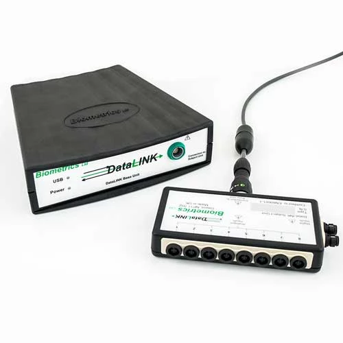
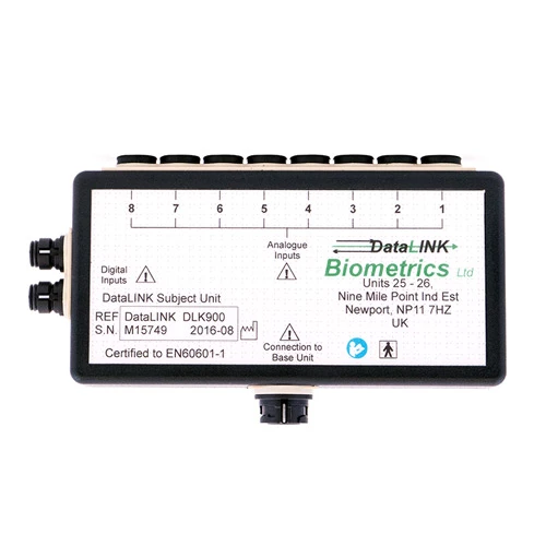
DataLINK Subject Unit
Sensors connect to a small, lightweight Subject Unit with both programmable instrumentation amplifiers and power supply responsible for energising the sensors, sampling and converting the inputs into a digital output. The data is transferred from the Subject Unit to the tabletop Base Unit via a RS485 data transfer cable. This cable (type no. R7000) is 7 metres in length but may be specified any length up to 20 metres. The Base Unit connects to the PC using a USB port where the data may readily be stored on disk or passed real time into other applications such as Microsoft Excel or Microsoft Visual Basic using the DLL (dynamic link library). Analog outputs may be obtained using an optional output cable (R2000i) attached to the Base Unit allowing the DataLINK to be interfaced to virtually any analog data recording system.
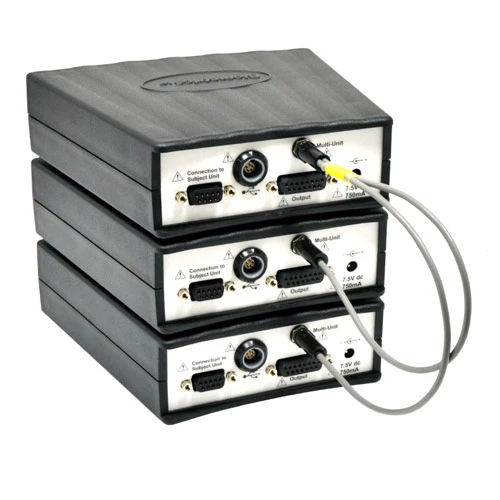
DataLINK Management Software
The DataLINK Management Software may simultaneously control up to 3 of the latest DataLINK units (manufactured after September 2013) giving the researcher the flexibility of up to 24 analog channels and 12 digital channels, by using either an SL200 or SL300 cable.
A real-time clock is included to enable every recording to be marked with an accurate start date and time along with its duration.
DataLINK Inputs
DataLINK comes with 8 analog inputs, accommodating both single ended voltage inputs and differential voltage inputs, and with 5 digital inputs, and the DataLINK Management Software.
Each input channel is individually controlled and configured within the versatile and easy to use DataLINK Management Software. Options for the analog inputs include selectable gain, selectable sampling frequency, selectable sensor supply voltage, and selectable zero or threshold level and selectable hysterisis level.
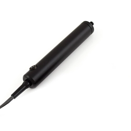
Event Markers
These useful accessories allow time marks to be registered in the recorded data. The events are marked for the duration of the time the switch is pressed:
- IS2 - A 1.8 metre cable with a suitable connector at one end to connect to the DataLINK Subject Unit, and a hand held switch on the other. This useful accessory allows time marks to be superimposed on the recorded data and enables the operator to highlight specific events during data collection.
- IS2-LED – Same as the IS2, but with a LED built into the hand held switch for use to activate start recording for precise synchronization with camera based motion analysis systems.
Multi Unit Cables
- SL200 - Used for connecting two DataLINK units to achieve up to 16 channels synchronization. Compatible only with the latest DataLINK units (manufactured after September 2013).
- SL300 - Used for connecting three DataLINK units to achieve up to 24 channels synchronization. Compatible only with the latest DataLINK units (manufactured after September 2013).
Synchronization Cables
- SYNC1 - For remote start / stop by a signal sent from other hardware systems to synchronize data collection from multiple sources. The SYNC1 is a 2 meter cable with a connector at one end to connect to the digital input socket of the DataLINK and 2 flying wires at the other end. Alternatively, this cable may be specified with any connector of choice. Please enquire with your specific requirements.
- SYNC1BNC - A synchronization cable with a BNC connector fitted for interfacing to certain 3rd party systems such as Qualisys or Vicon. Connector chassis is wired as common or ground. NOTE: Please contact Biometrics Ltd or the 3rd party equipment manufacturer for specific instructions before this cable is used.

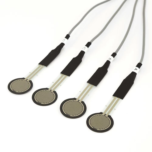
Contact Switch Assembly
- FS4 - An assembly of 4 Force Sensing Resistor Sensors (FSRs) each on 1.2 meters of cable which are readily connected to the DataLINK via one connector for use as switches to indicate contact e.g. heel and toe strike or palmer contact. The sensors are thin and robust and are usually placed inside the subject's shoe or glove for convenience.
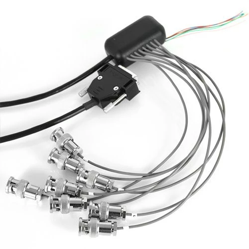
Analog Output Cable with BNC Connectors R2000iBNC
The optional cable R2000iBNC has 8 BNC connectors for connection to a range of proprietary AD boards. This allows realtime analog data transfer of up to 8 channels per DataLINK unit directly into other hardware for synchronization with other inputs - for example integrating surface EMG measurements collected by the DataLINK into video motion capture systems.

DataLINK Laboratory Systems
DataLINK laboratory systems are comprehensive packages of sensors and instrumentation for static & dynamic measurements in clinical settings, research centres, or any remote location such as a workplace.