
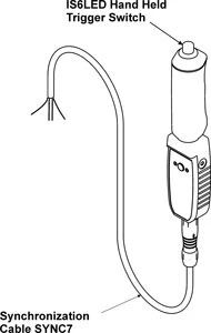
Hand Held Trigger Switch

The Known Problem
In general, when a recording is made using 2 digital systems, it can be very difficult to synchronize the systems due to:
- communication delays which are inherent using all PC operating platforms, including Microsoft Windows, and
- differences between the 2 quartz system clocks. For example, two quartz crystal controlled watches accurate to say 1 second per day, perfectly synchronized at time zero will be out by over 40mS after 1 hour.
The Biometrics Ltd Solution
Recordings made using DataLITE along with another recording system can be very accurately synchronized using the DataLITE Trigger Switch.
This provides timing signals that can be used to correct for small variations in start times and internal clocks between the different units used.
Synchronization & Event Marking

Product Specifications
| Dimensions | 29 x 29 x 153mm | Mass | 80g |
|---|---|---|---|
| Communication with PC/Laptop | Wi-Fi | Sampling rate | User select 2000, 1000, or 500 samples per second |
| Accuracy | ≤ 3mS | Power source | Rechargeable Li-ion Polymer Battery |
| Wireless transmission data loss | Tolerant for 120mS | Wireless Range | Up to 30m |
| Wireless Interface | DataLITE PIONEER, ADVANCE, EXPLORE | Wired Interface | DataLOG or other 3rd party system (see below) |
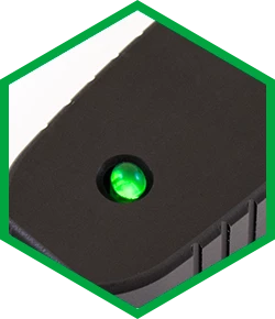
A large green LED for accurate synchronization with 3rd party camera-based recording systems
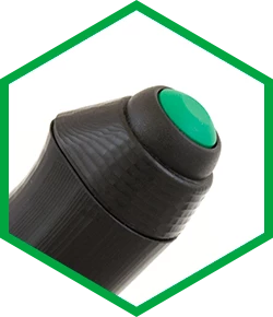
A top mounted large button to start and stop a recording. This button can be programmed to be used as a trigger switch during recording instead of stopping the recording
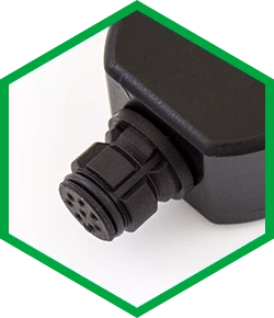
A socket mounted at the bottom of the unit which is used for wired electrical synchronization with a 3rd party system
Connecting With Other Systems
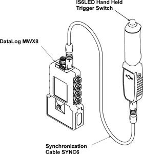
When the Trigger Switch is used with a Biometrics Ltd DataLOG, any discrepancies in timing are automatically aligned within the DataLITE software application when the 2 files are loaded.
The Trigger Switch is easily connected to the DataLOG using cable REF SYNC6 as shown.
The Hand Held Trigger Switch is readily connected to a 3rd party system using cable REF SYNC7 as shown to the right. One end of the cable connects to the socket at the bottom of the Trigger Switch and the other end is connected to the 3rd party system.
This connection to the 3rd party system is a 4 wire cable details as follows:
| Wire Colour | Description |
|---|---|
| Black | Common (+0V) |
| Brown | Event Mark Output from DataLITE level (+3V) switching to level invert (+0V) |
| Orange | Event Mark Output from DataLITE level invert (+0V) switching to level (+3V) |
| Red | TTL Event Mark Input to DataLITE from 3rd party system level (+3V) switching to level invert (+0V) |
Recording
The following schematic explains in detail the timing commands in relation to start recording and stop recording.
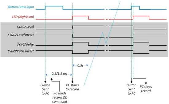
The 2 programmable digital outputs for synchronous start/stop of other recording systems are available using the SYNC7 cable. One is the inverse of the other and they may be programmed to be level or pulse output. Refer to the schematic to the left.
- The 4 sync output waveforms shown with a grey background show the output options available by programming level or pulse outputs.
- These digital pulses allow the Trigger Switch to be used as a master to start & stop the recording of the 3rd party system. Alternatively, they may be used to place an even mark into the other system.
- The large green LED may be used to visually mark the start & stop of recording.